Free L1 sample questions
Questions from the Advanced Engine Performance Specialist practice bank, with the correct answer and an explanation for each one. No junk, no filler.
Try them in the simulator Same questions, with study, timed and flashcard modes.
Showing 6 of 12 free sample questions.
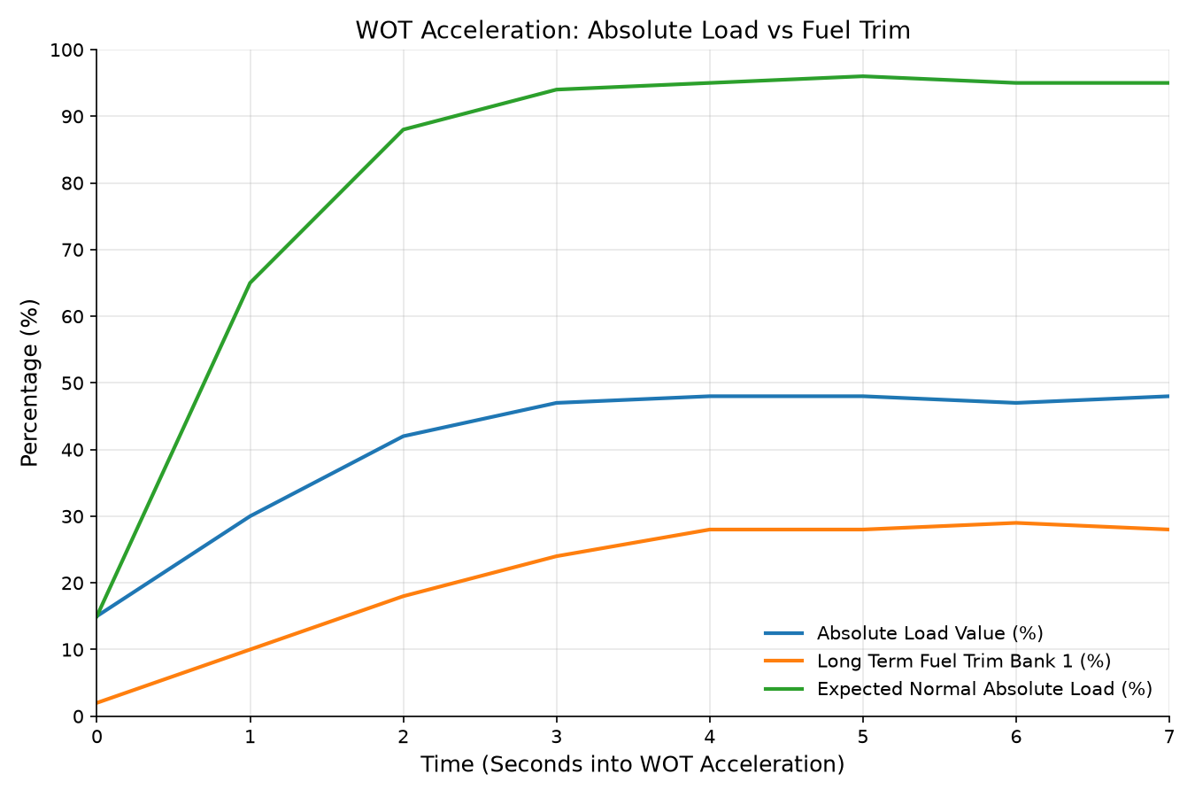
A Composite Vehicle Type 4 exhibits poor acceleration and a lack of power under wide-open throttle (WOT). The technician records the scan tool parameters shown in the accompanying chart during a full-throttle road acceleration run from 25 mph to 60 mph. Based on the relationship between Absolute Load Value, engine RPM, and Long Term Fuel Trim, which of the following components is the root cause of the driveability concern?
A technician is diagnosing a total communication loss on the Powertrain Communications Network of a Composite Vehicle Type 4. With the vehicle battery disconnected, an ohmmeter connected between DLC terminal 6 (Data-High) and DLC terminal 14 (Data-Low) reads infinite resistance (OL). What does this reading indicate? graph LR DLC[DLC Pins 6 & 14] --- Bus[CAN High / Low Bus] Bus --- R1[ECM Terminating Resistor 120 Ohms] Bus --- R2[Cluster Terminating Resistor 120 Ohms]
A scan tool fails to communicate with any module on a Composite Vehicle Type 4. A digital storage oscilloscope connected to DLC pin 6 (Data-High) displays a constant 0.0 V flatline. When the Instrument Cluster is disconnected, the pin 6 voltage remains 0.0 V and resistance to ground remains 0 Ω. When the ECM harness is disconnected, the resistance from DLC pin 6 to ground changes to infinite (OL). What is the root cause of this failure?
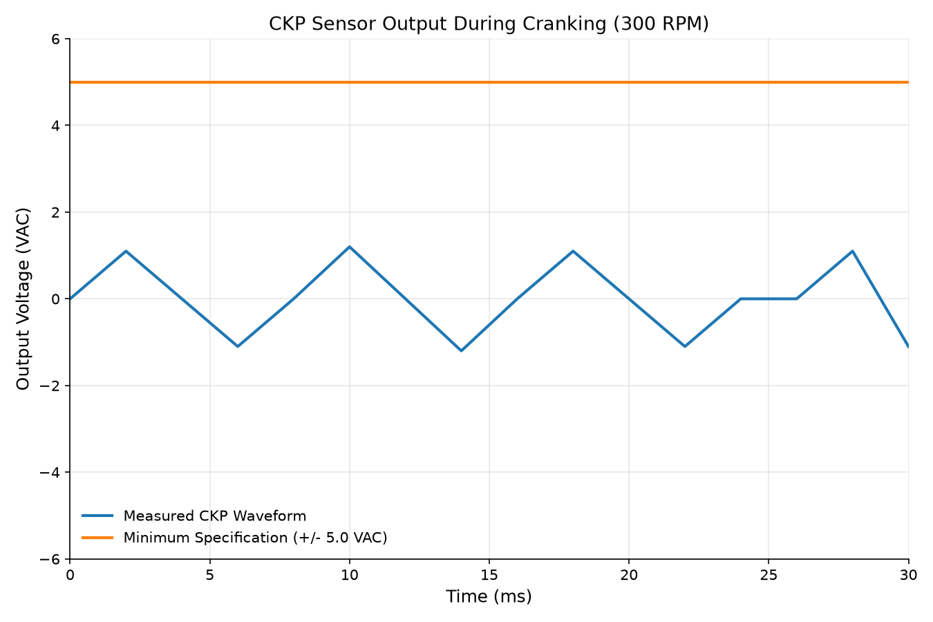
The engine of a Composite Vehicle Type 4 cranks normally at 300 rpm but will not start. The technician connects a digital storage oscilloscope to test the Crankshaft Position (CKP) sensor. The captured AC voltage waveform during cranking is shown in the figure. Specifications state that the variable reluctance CKP sensor must produce at least 5.0 VAC minimum. What is the cause of this abnormal waveform?
On the Composite Vehicle Type 4, the throttle body incorporates dual opposing Throttle Position Sensors (TP 1 and TP 2). When the electronic throttle plate is actuated to exactly 50% throttle angle, what voltage should be measured on each sensor signal wire?
6 more free samples are waiting
Create a free account to unlock the whole L1 sample bank, or get full access to all 160 practice questions in the simulator.